

Send your location + project type + rough dimensions
We’ll reply with a project-specific recommendation and factory-direct quote within 24 hours.
This glass balustrade UK project combined a structural balustrade with custom cabinetry for a lakeside residence. The case study covers the engineering behind aluminum U-channel glass mounting systems, the BS 6180 compliance approach for residential barriers, and why multi-scope projects — where balustrade and joinery share the same visual field — require tighter dimensional coordination than single-product installations.
Project Overview
- Location: Lakeside, United Kingdom
- Products: Glass Balustrade (U-Channel System), Custom Kitchen Cabinetry
- Balustrade Materials: 6063-T5 Aluminum U-Channel Base, 10mm Toughened Glass, Structural Silicone Sealant
- Cabinet Materials: 18mm MDF Carcass, Spray-Painted Finish (RAL matched)
- Guardrail Height: 1,100 mm — BS 6180:2011 compliant for domestic floors
- Project Type: Residential
- Completed: 2023
The Challenge
This project was unusual because it combined two normally separate procurement scopes — glass balustrade and kitchen cabinetry — into a single coordinated package. In a lakeside residence with open-plan living, the balustrade and the kitchen joinery occupy the same visual field. If their finish tones, surface textures, or geometric alignments diverge by even a few millimeters, the result reads as two separate installations forced together rather than a coherent interior.
The balustrade needed to comply with BS 6180:2011, the British Standard for barriers in and about buildings. For domestic floors above ground level, BS 6180 requires a minimum barrier height of 1,100 mm (compared to 900 mm for stairs). The standard also mandates that the barrier resist a horizontal line load of 0.36 kN/m applied at the top, plus an infill load of 0.5 kN/m² applied over the glass panel area. For a U-channel system, these loads transfer from the glass through the structural sealant and rubber gaskets into the aluminum channel, and then through the channel anchors into the structural floor — a load path that requires each component to be correctly sized and installed in the right sequence.
The additional complexity was tolerance management. The cabinetry was factory-built to ±1 mm precision, which is standard for modern CNC-routed kitchen furniture. The balustrade needed to match that level of precision at its interface points — where the glass panel ends near a cabinet wall, or where the U-channel terminates against a joinery unit. Conventional construction tolerances of ±5 mm for metalwork would have produced visible misalignments at these junctions.
Project Gallery
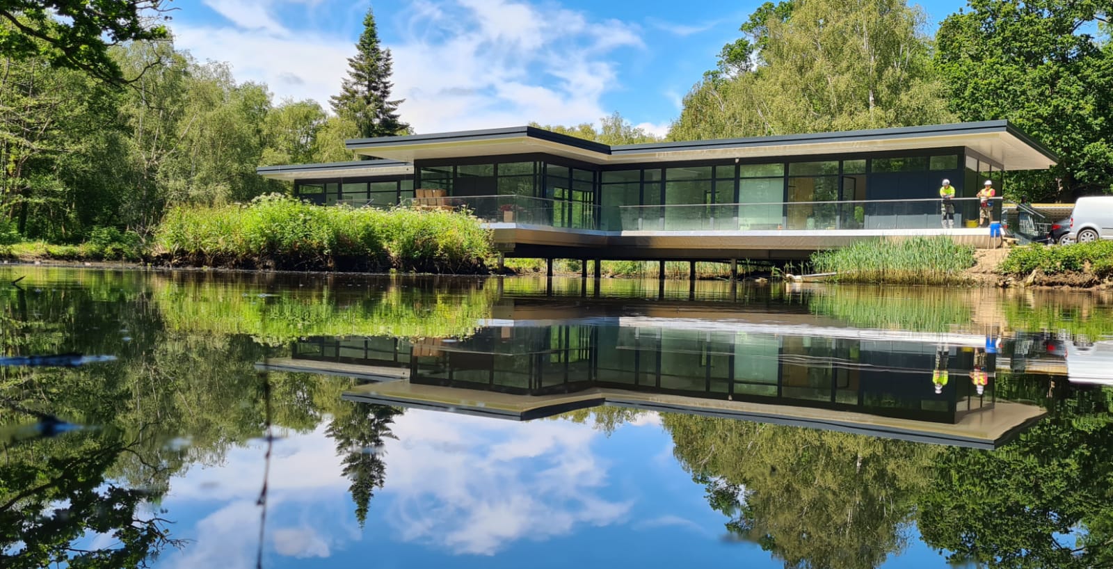
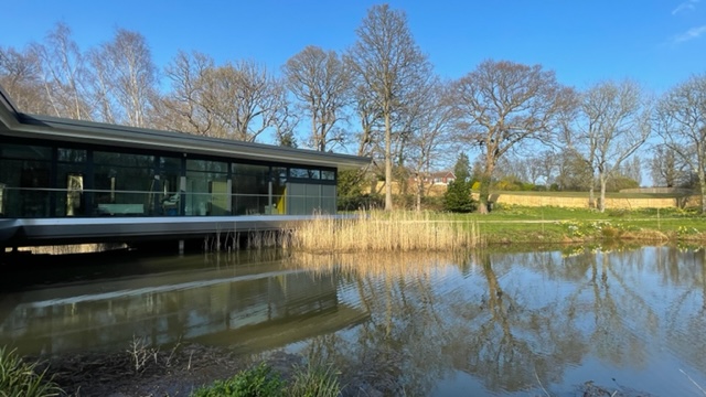
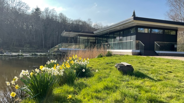
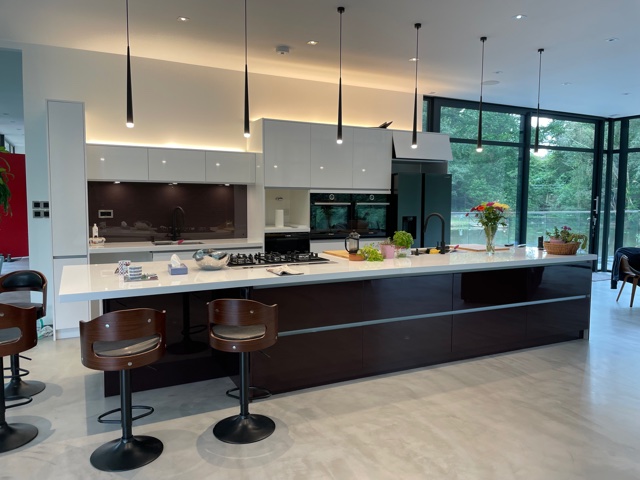
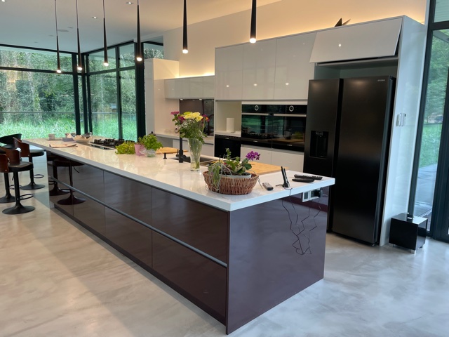
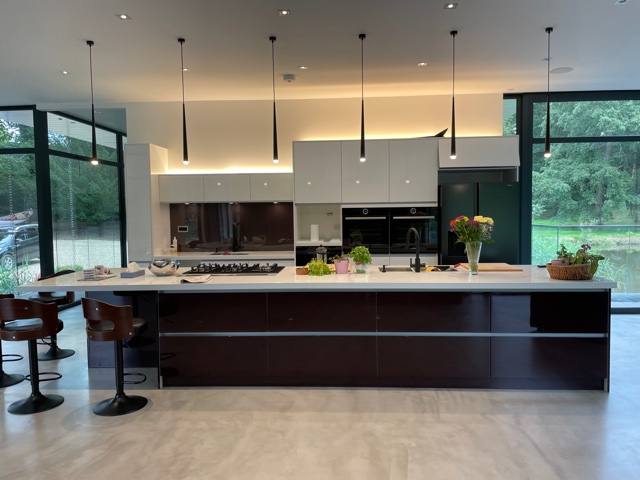
The hero image shows the balustrade and cabinetry sharing the open-plan space. The aluminum U-channel at the glass base maintains a low profile that does not compete with the cabinet hardware lines. The glass panel height is set to the BS 6180 required 1,100 mm, with the channel adding approximately 50 mm below the glass for a total assembly height that accounts for the floor buildup.
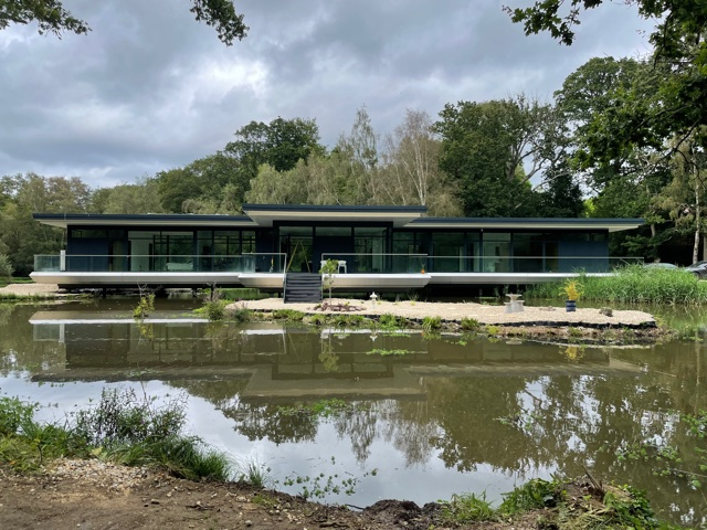
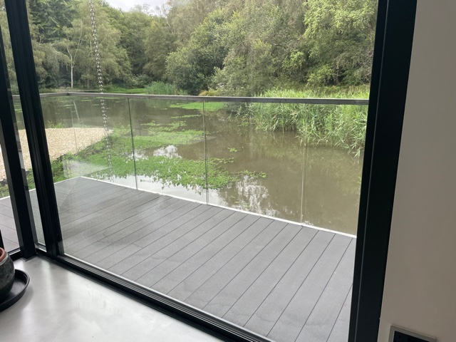
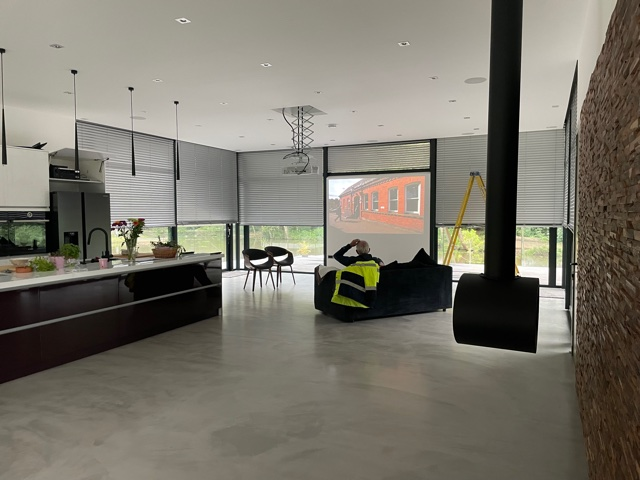
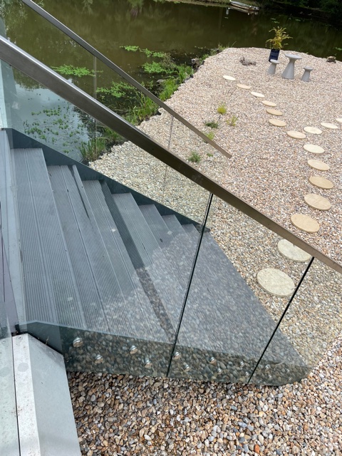
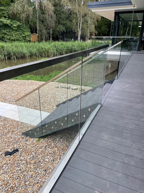
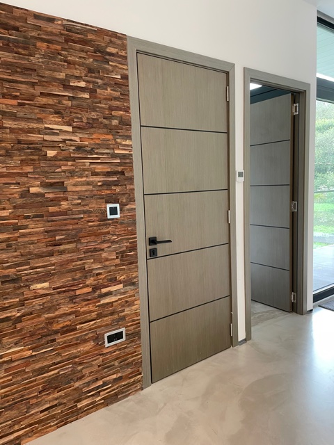
The detail images below document the critical junction points. Pay attention to the gap between the U-channel termination and the adjacent cabinet panel — this is a precision interface that was coordinated using a shared dimensional control drawing before either the balustrade or the cabinetry went into production. Our glass railing systems use parametric channel profiles that can be trimmed to site-verified dimensions, which simplifies the tolerance management when interfacing with millwork from a separate supplier.
Our Solution
We designed the balustrade and cabinetry from a shared baseline — literally the same dimensional control drawing, with a common datum line that both the U-channel layout and the cabinet carcass dimensioning referenced. This eliminated the coordination gaps that typically appear when a glazier and a cabinet maker work from independent drawings.
U-Channel System Engineering
The aluminum U-channel is the structural backbone of this balustrade type. Unlike spigot systems where each point fixing carries load independently, a U-channel distributes the glass panel loads continuously along the channel length. For this project:
- Channel profile: 6063-T5 aluminum alloy, 50 mm depth × 21 mm internal width (sized for 10mm glass plus gaskets). The T5 temper provides a yield strength of approximately 110 MPa — adequate for the BS 6180 loading at this barrier height and panel width.
- Glass retention: Each panel sits on two EPDM rubber setting blocks at the quarter points (positioned at 25% of panel width from each edge), with continuous EPDM wedge gaskets on both sides of the glass. After gasket insertion, a structural silicone bead (neutral-cure, ASTM C920 Type S) was applied along the channel top edge as a secondary retention measure.
- Anchor spacing: The U-channel was fixed to the concrete floor slab using M8 stainless steel Rawl anchors at 400 mm centers — approximately half the maximum spacing permitted for this loading condition, providing a meaningful safety factor.
- 10mm toughened glass: For the panel widths used in this project (800–1,000 mm between supports), 10mm toughened glass is adequate under BS 6206 impact classification and BS 6180 barrier loading. Each panel was edge-polished to a flat finish rather than arrissed, which produces a cleaner visual edge where the glass meets the channel top.
Cabinetry Coordination
The kitchen cabinets were manufactured as 18mm moisture-resistant MDF carcasses with spray-painted doors and panels finished to a RAL colour selected to complement the aluminum channel’s natural anodized tone. The critical coordination points were the three locations where a cabinet end panel directly abuts or faces a balustrade termination — at these junctions, we held a maximum tolerance of ±2 mm and used a shadow gap detail (6 mm nominal) to create a clean visual separation rather than a butt joint that would amplify any misalignment.
Delivery & Installation
Multi-scope packages demand a specific installation sequence — the wrong order creates rework. For this project, we specified a three-phase site sequence:
Installation Sequence
- Phase 1 — U-Channel and Anchors: The aluminum channel was installed first and surveyed to confirm it was level within 1 mm over each 2 m run. This established the baseline for both the glass panels and the adjacent cabinetry. The channel acts as the dimensional master — everything else references it.
- Phase 2 — Cabinetry Carcasses: Kitchen carcasses were installed next, with their datum heights and positions verified against the channel survey. The shadow-gap detail at each balustrade junction was checked before doors and panels were fitted.
- Phase 3 — Glass Panels and Silicone: Glass panels were installed last, after all adjacent construction was complete. This protects the glass from construction damage and allows the installer to verify final clearances against the as-built cabinetry positions.
All components were packed to support this sequence. The U-channel sections and anchor kits were in Crate 1 (first to arrive on site). Cabinet components were in Crates 2–4 (organized by kitchen zone). Glass panels were in Crate 5 (last to open, with edge protection maintained until the moment of installation). For projects where the balustrade interfaces with stair openings or level changes, our stair and railing coordination reference provides additional sequencing guidance for multi-trade installations.
The Result
The completed interior reads as a single design language. The glass balustrade preserves the open sightlines to the lake — which was the fundamental reason for choosing glass over solid barriers — while the cabinetry provides functional storage without introducing visual clutter. The RAL-matched paint finish on the cabinet doors sits comfortably alongside the anodized aluminum channel, with the 6 mm shadow gap at each junction creating a deliberate separation that looks intentional rather than accidental.
Structurally, the U-channel system meets BS 6180:2011 requirements for domestic barriers at 1,100 mm height. The continuous channel profile distributes loads more evenly than point-fixed systems, which reduces stress concentration at individual anchor points — an advantage that matters more in retrofit situations where the existing floor slab may have unknown reinforcement patterns. The 400 mm anchor spacing provides an additional safety margin above the calculated requirement.
The project demonstrates a procurement approach that many residential clients overlook: by sourcing the balustrade and cabinetry through a single coordination point, the homeowner avoided the dimensional conflicts and finger-pointing that commonly occur when separate suppliers install adjacent elements without a shared reference drawing. The total coordination effort added roughly two weeks to the pre-production schedule but eliminated the rework and site adjustments that typically consume more time and cost than the upfront coordination.
Sources & Disclaimer
- Project documentation, photography, and engineering data from Double Building Materials internal records.
- Material specifications verified against manufacturer data sheets for 6063-T5 aluminum alloy, 10mm toughened glass conforming to BS EN 12150, and 18mm moisture-resistant MDF.
- Building code references (BS 6180:2011, BS 6206, Building Regulations Part K) are for general guidance only; always confirm requirements with your local Building Control Body (BCB) or Approved Inspector.
Disclaimer: This case study is published for informational and portfolio purposes. Actual project specifications, timelines, and costs vary by location, scope, and site conditions. Multi-scope projects require early coordination — contact us to discuss combined balustrade and joinery packages for your project.